CAM, tools & machines
Machining planning, tool data, setups, 2D/3D toolpaths, simulation, collision findings, post-processors, programs and controlled transfer to target machines form a connected technical chain.
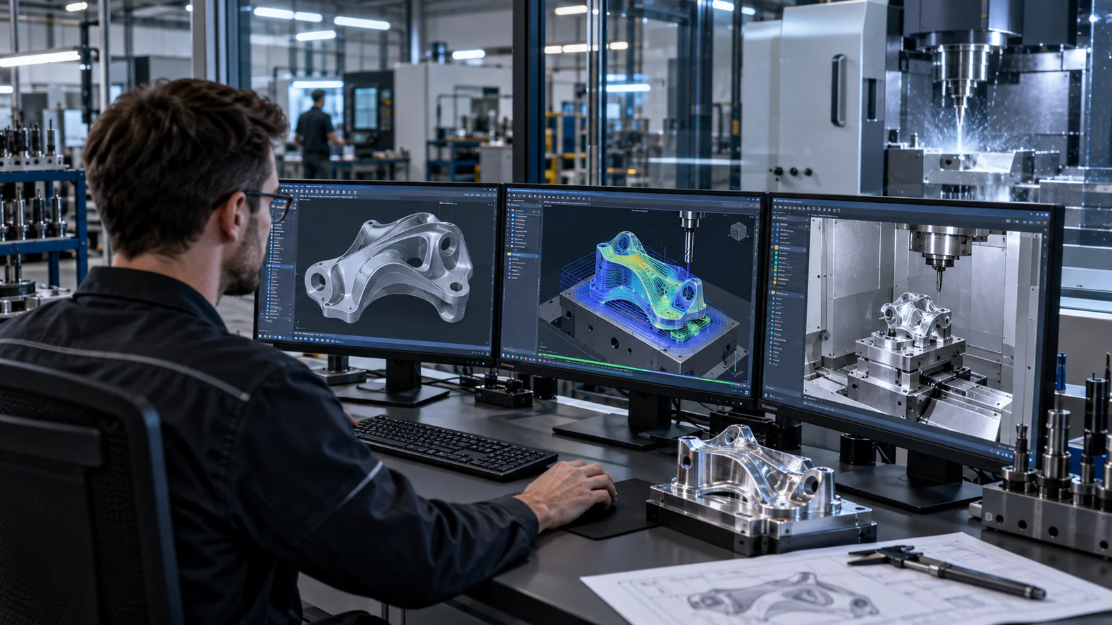
Today, every CAM program is built from scratch.
Tools, setups, strategies and post-processor output are defined by hand again and again for similar parts – and in the worst case, collisions are only noticed at the machine.
- Selecting tools and cutting parameters anew for each order
- Clarifying setup, work zero and clamping fixtures verbally
- Reprogramming operations and sequences
- Triggering simulations and collision checks individually
- Transferring programs to the machine by hand
What the module covers.
Tools & holders
Maintain tools, magazines, holders, materials and cutting parameter ranges per machine.
Setups
Define and confirm stock, position, work zero, clamping fixtures and safety zones.
CAM operations
Parameterize roughing, finishing, sawing and other operations with versioning.
Simulation & material removal
Simulate calculated toolpaths; evaluate before/after/rest material.
Collision check
Take tool, holder, part, clamping fixtures, axes and available machine geometry into account.
Post-processor & program
Version, verify and transfer machine-specific output and make it traceable with checksums.
From intake to a controlled result.
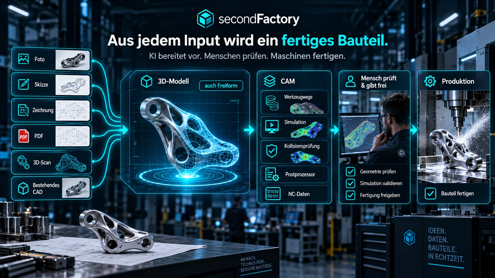
This is where your team reviews and decides.
secondFactory prepares. At these points, a person confirms, corrects or deliberately approves – nothing slips through unnoticed.
Confirm setup
Stock, work zero, clamping fixtures and safety zones are confirmed before calculation.
Evaluate simulation
A skilled expert reviews toolpaths, material removal and collision findings.
Approve program
A human confirms CAM and program before the NC program and setup package go to the machine.
What improves day to day.
Less CAM routine
Prepare recurring strategies and parameters.
More safety
Simulation, collision checking and approvals before machine start.
Machine-specific
Version profiles, post-processors and transfer targets.
What goes in. What comes out.
Input sources
- Approved geometry from engineering & CAD
- Tools, holders, magazines and materials
- Stock, work zero and clamping fixtures
- Machine profile and available machine geometry
- Post-processor of the target machine
Results
- Versioned CAM operations
- Simulated toolpaths with material removal
- Collision findings
- Machine-specific NC program with checksum
- Setup package for the machine
Handovers without re-entry.
Engineering
Approved 3D geometry and technical documents.
CAM, Tools & Machines
From geometry to a checked machine program.
Production
The NC program and setup package are sent to the target machine in a controlled way.
Check CAM & machines on a real part.
In a process analysis, we walk through a typical part from geometry to machine program – with your tools and machines.