
Engineering, CAD & Technical Data
Technical cases bundle geometry, parameters, sources, revisions, corrections and approvals. From these, sketches, 2D/3D data, CAD adapters and customer-specific design logic can derive production-ready documents – including freeform shapes, if the data and methods are suitable.
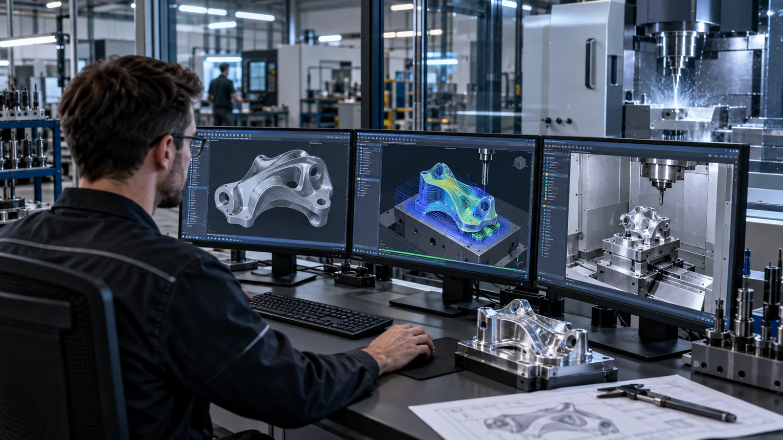
Today, similar parts are designed from scratch again and again.
Many components resemble known parts. Even so, geometries are rebuilt, dimensions are retyped from documents, and bills of materials and documents are compiled one by one.
- Rebuilding similar models
- Transferring dimensions and parameters from drawings
- Maintaining bills of materials and assemblies manually
- Deriving tool and mold making components by hand
- Tracking revisions in file names instead of traceably
What the module covers.
Sketches & 3D models
Create or import parametric sketches, plan sections and 3D geometries.
Revisions & versions
Version changes; do not silently overwrite approved versions.
Dimensions & sources
Check parameters, units, cutouts, orientation and origin.
CAD integrations
Integrate STEP, STL, OBJ, DXF and customizable CAD adapters into technical workflows.
Design logic
Add bills of materials, assemblies, tool/mold making or industry-specific generators on a rule basis.
Engineering approval
Present geometry to the employee for review, document corrections and approve selectively.
From intake to a controlled result.
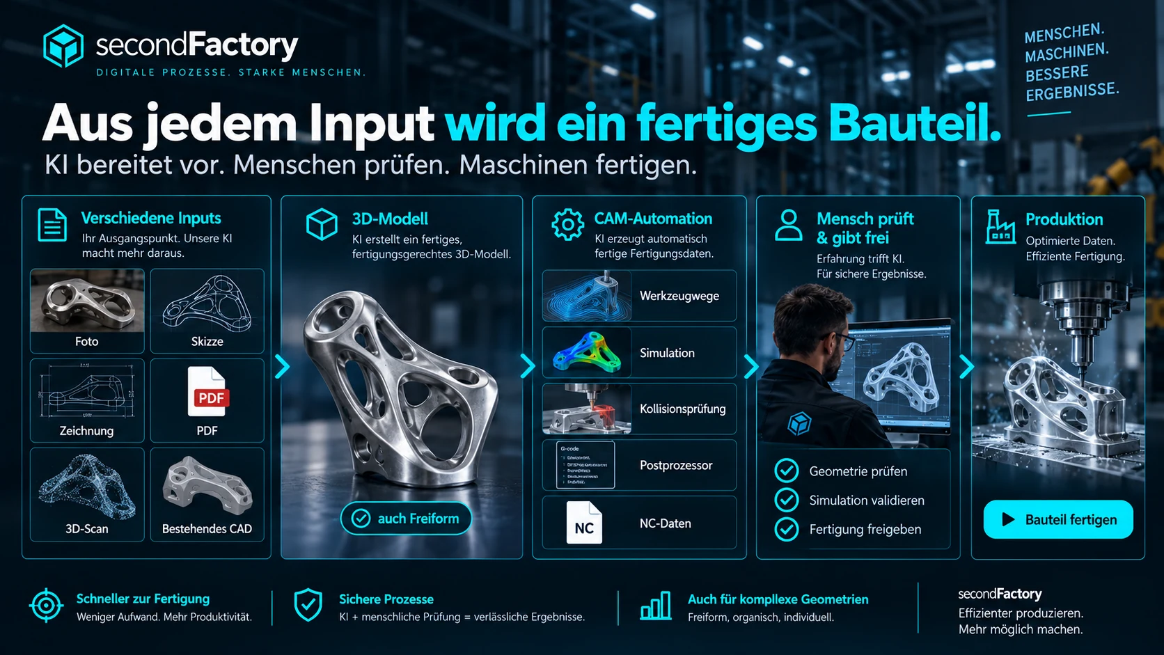
This is where your team reviews and decides.
secondFactory prepares. At these points, a person confirms, corrects or deliberately approves – nothing slips through unnoticed.
Check geometry and dimensions
3D model, dimensions, bodies and orientation are technically reviewed before being passed on.
Confirm domain logic
Rule-based derived bills of materials, assemblies or mold making components are checked against your standards.
Approve engineering
Corrections are documented; approved versions are not silently overwritten.
What improves day to day.
Less rebuilding
Automate recurring geometry and derivations.
Better consistency
Keep technical data consistently versioned.
Openly extensible
Integrate your own generators, CAD systems and industry logic.
What goes in. What comes out.
Input sources
- Photos, sketches and scans
- Drawings as PDF or on paper
- CAD data: STEP, STL, OBJ, DXF
- Parameters and company standards
- Requirements from inquiry & quote
Results
- Parametric or freeform 3D geometry
- Versioned revisions
- Checked dimensions with source reference
- Bills of materials and assemblies
- Tool and mold making derivations
- Approved technical documents
Handovers without re-entry.
Inquiry and planning
Drawings, requirements and order data from inquiry and planning.
Engineering, CAD & Technical Data
Any suitable input becomes reliable geometry.
CAM and material
Approved geometry goes to CAM & Machines, material requirements go to Material & Nesting.
Check engineering on a real part.
Bring a typical drawing, photo or CAD model. We show what secondFactory prepares from it and where your design engineers approve.